ER is a tool that you can use to configure formats for both incoming and outgoing electronic documents in accordance with the legal requirements of various countries/regions. ER lets you manage these formats during their lifecycle. For example, you can adopt new regulatory requirements, and generate business documents in the required format to electronically exchange information with government bodies, banks, and other parties. In this blog, general overview of ER components will be covered, together with a tutorial presenting a way how to add financial dimension to an existing electronic report.
Electronic reporting components
Electronic reporting (ER) supports the following types of components:
- Data model
- Model mapping
- Format
- Metadata
Data model component
A data model component is an abstract representation of a data structure. It describes a specific business domain area in enough detail to satisfy the reporting requirements for that domain. A data model component consists of the following parts:

The business entity of a data model is represented as a container, or record. Business entity properties are represented as data items, or fields. Each data item has a unique name, label, description, and value. The value of each data item can be designed so that it’s recognized as a string, integer, real, date, enumeration (enum), or Boolean value. Additionally, the data item can be another record or record list.
Model mapping component
Model mapping links application data sources to individual elements of a data model that specify, at runtime, the data flow, and rules for entering business data in a data model component. It can use different data types as data sources for a data model. These data types include tables, data entities, methods, and enums. It supports user input parameters that can be defined as data sources for a data model when some data must be specified at runtime (for example, which financial dimension to be included). Also filtering, sorting and other operations are supported, but only for outgoing documents.
Format component
A format component is the scheme of the reporting output that is generated at runtime. A scheme consists of a format that defines the structure and content of the generated electronic document, data sources, format mapping as a set of bindings and a format validation as a set of configurable rules that control report generation at runtime. For example, there might be a rule that stops output generation of a vendor’s payments and throws an exception when specific attributes of the selected vendor are missing, such as the bank account number.
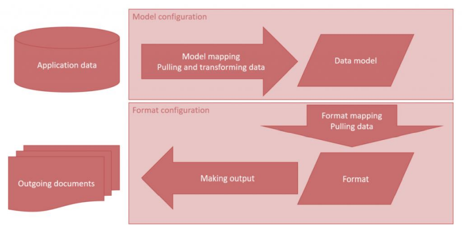
Created reporting output can be as individuals file in various formats, such as text, XML, Microsoft Word document, or worksheet. But there is also a possibility of creating multiple files separately and encapsulating them into zip file. The following illustration shows how the data flows in outgoing report.
Problem description
In France each company has to deliver so-called FEC report to the government. It is an export of several entities having a specific format. The format is very strict, that means when it is not correct, the declaration will not be approved. The FEC report is available in F&O as part of the electronic reporting functionality, a localization made for France. However, the export of the ledger transactions is based upon the Main account.
In France you need a specific local chart of account. Imagine that this account is stored in a custom-made financial dimension called: FRACOA. The main goal is to replace main account values with FRACOA values. To be more precise, the account number (CompteNum) should be replaced with the dimension’s value, while account description (CompteLib) should be replaced with the dimension’s description.
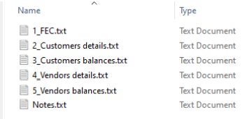
The report’s output format is a ZIP file containing 5 text
documents. Only the values in the first document called
1_FEC.txt need to be replaced.
Solution
Because the ER already exists and it’s part of Microsoft standard configurations library, we do not want to create a new model, but rather to create a duplicate of the existing one. In that way, we can do modifications on it.
Modifications of an existing electronic report can be done only on a duplicated version of it. You are not allowed to change or modify existing standardized configurations.

The FEC report is located under the configuration named
‘Data export model’. As we can see, it consists of a model
definition, model mapping and two report designs (German
and French localization).
If you are missing the configuration for your report, then first you should go to Workspaces > Electronic reporting > from Configuration providers select Microsoft and click on Repositories > select Global and click Open > find the desired model and click Import/Import all (depending on if you would like to import everything or just particular configuration).
If we take a look at the design of the data model, we can see that it has quite a complex structure unlike ones that are usually used. Fields that will be included in the final report are rather dynamically structured and, in the model, we just define some fundamental nodes so they can fetch the data. In this model, all fields are implicitly defined, contrary to most of the models where nodes (fields) are explicitly defined. The Tables node defines files from the zip, while in Records is defined the structure of records in one file. If we expand one of the (*)Fields node, we can only see some type of rules to check what type is the value in the field, to cast it in the appropriate type and some additional metadata for the field.

This means that the model is pretty conserved and made to be generic. We do not need to change anything here. Thus, there is no need of duplicating the data model. Instead, we need to duplicate the model mapping and do our changes there.
Duplicating the data model mapping
- Make sure you are located in Workspaces > Electronic reporting > Reporting configurations > locate and expand the desired model in the tree, in our case it is ‘Data export model’
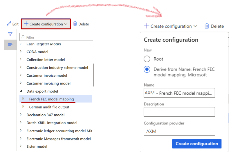
- Select the model mapping, in our case it is ‘French FEC model mapping’ and click on Create configuration
- In the drop dialog, for the New field select ‘Derive from Name: French FEC model mapping, Microsoft’. In the Name field, type the name for the mapping ‘AXM – French FEC model mapping’. In the Description field, you can set a description, but it is not mandatory. Click Create configuration.
Map the model to use financial dimensions
- In the tree, select the newly created model mapping ‘AXM – French FEC model mapping’ and click on Designer in the action pane.

- Since we are creating a duplicate instead of new mapping, in the grid there should already be a record for the mapping – copy of the original one. Select it and click Designer.

- In the Model mapping designer form, it can be seen that there are already some data sources defined. Those data sources are used for the current implementation of the report. First thing we need to do is to add the data source for using financial dimensions for this report.
- In the tree, select ‘Functions\Financial dimensions details’ and click Add root. This data source specifies how the scope of financial dimensions will be defined for any report that will use this model as a data source.
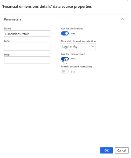
- In the Name field, type a value. Select Yes in the Ask for dimensions field (select Yes to allow the user to select dimensions at run-time on the User dialog form. If set to No, all financial dimensions of the current instance will be used by default).
- In the Financial dimensions selection field, select ‘Legal entity’ (select All to allow the user to select desire dimensions for the current instance in the Lookup field. Select Legal entity to allow the user to select dimensions for the company in the Lookup field. Select Dimension to allow the user to select dimensions using a single dimension set.
- Select Yes in the Ask for main account field (set ‘Ask for main account’ to Yes to allow users to select the main account as part of the list of dimensions. If set to No, the main account will not be included to the list of dimensions and the ‘Is main account mandatory’ option is enabled. If “Is main account mandatory’ is set to Yes, include the main account in the list of dimensions regardless of the user’s selection).
- Click OK.
- The newly created data source should be visible among other data sources in the middle section of the form.

- If we take a closer look at data sources and data model, we can see that Tables node in the data model is bonded to the TblGroup data source. This data source is actually a calculated field that serves as a bridge between the model and the data source named TblGroup1. We need to find the source of data providing and in this case that is the data source ‘FEC files with details(TblGroup1)’. This data source is defined using specific function (Dynamics.AX.Application.ERModelGDPdUFunction). By expanding it, we cannot add fields or change mapping because its structure is generic too.
If you cannot see details about data sources binding and inheritance, click on Show details button in the main action pane. - Select FEC files with details(TblGroup1) and click on Edit button in the ribbon.
- A new dialog will appear showing data source parameters. In addition, there is a button named Editor which allows us to enter the editing mode for making changes in the structure of the report. Click on Editor.
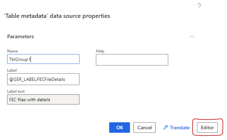
- Table Metadata form is opened. This form is divided into three parts:
- Tables (most left section) where all files are being present. In this grid the name of the table (file) is being shown together with a path relating to a particular data source.
- Fields (middle section) where all fields related to a selected table from the left grid are being shown. In this grid, the name of the field is being shown together with a path relating to a particular node in a data source.
- Data sources (right section) where all active data sources for the desired model are being shown. Above the grid, there is an Add button. Using this button, we can find the field we want in any active data source and add it in the desired table.
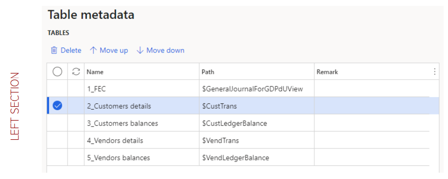


If you are not able to see all sections, zoom out the browser settings.
- Select the desired table in the left section. In our case, because we need the change to be applied only to the 1_FEC.txt file, we select the table 1_FEC.
- In the middle section, select fields you would like to replace. In this case, we select CompteNum and CompteLib. Click Delete.
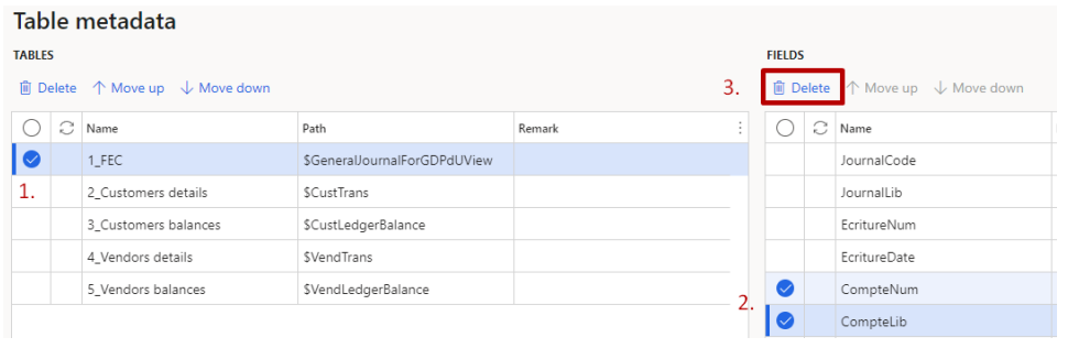
- In the right section, expand the general journal entry where financial dimensions are stored. In this case, we expand $GeneralJournalForGDPdUView data source. If you are not sure which data source to use, take the one that other fields from the same table are mapped from.
- Expand and select ‘$GeneralJournalForGDPdUView/getGeneralJournalAccountEntry() /LedgerDimension.Dimension/Main account and dimensions/Value/Code’.
- Click Add.
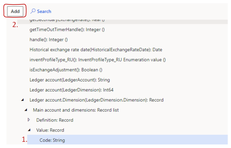
- Expand and select ‘$GeneralJournalForGDPdUView/getGeneralJournalAccountEntry() /LedgerDimension.Dimension/Main account and dimensions/Value/Description’.
- Click Add.
- New fields should be visible somewhere in the grid, under their original names. Click on the Name field with value ‘Code’ and change it to ‘CompteNum’. Change the value ‘Description’ to ‘CompteLib’.
- Using the Move up and Move down buttons, you can change the order of the fields in the grid. This is important because in same manner the fields will be shown in the output file.
- Save the changes. Click Close.
- Save the changes again and click Close.
- From the configuration tree, select the desired model mapping, in this case it is ‘AXM – French FEC model mapping’. Select the Draft version and click Change status.
- From the drop dialog, select Complete. If it’s the first time you are modifying the mapping. Now you will get two records in the gird, one that is Completed and one that is in Draft. After every change, if we want it to be reflected in the output, we need to set the latest draft version to Completed.
- In order the report to take our custom-made mapping, we need to set it as default. This way, the system will know what mapping to choose when running the report. Make sure the correct mapping is still selected.
- Click Edit and set the control Default model mapping to Yes.
Designing the report
If we open the format designer to see the structure of the report, we can notice that it is generic, same as the model itself. This means that no changes need to be done here as well. The advantage of using this approach for modeling reports is that the structure of the report is partially conserved, but if you do need to do some small changes, you only need to do changes into the mapping part.

Running the report
Depending how this report is set to be ran in standard environment, you can test it from there, or you can navigate to the configurations form and
- Expand the model we created mapping for and select the format that already exists, in this case it is ‘French FEC audit file’ and click Run.
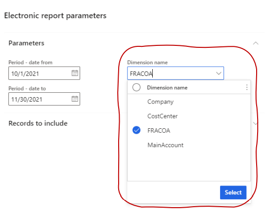
- In the Dimensions field, choose which dimension you would like to be shown in the output report instead of the main account number and click Select (if FRACOA dimension is chosen, then we will get its values in the report, otherwise if the MainAccount is chosen, then we will obtain the original report from before. This implementation gives flexibility in the way of execution. Note that the drop dialog to choose a dimension is not available in the original configuration of the report. This is customization that was implemented using this tutorial).
- After clicking the OK button, a zip file is being generated and downloaded to the local computer. The downloaded zip file has a structure similar to this:

- We can open the first text file and compare it with a previously downloaded version of the original report.

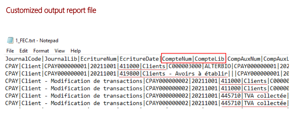
We can notice that the main account values are indeed replaced with FRACOA values for all entries. No changes were made to other 4 files so they will keep the same structure and data.
Following this tutorial, you should be able to do a modification on any report you need to. The most important thing is to understand the logic behind components of electronic reports and their binding. In a situation where the model and the format have explicit structure and mapping from data sources is done directly, creating the desired mapping has a little bit more work to be done. You just need to stick to the following sequence:
Create duplicate of a model > Create the node you would like to be shown in the output (make sure you create it under the correct parent node) > Create duplicate of the model mapping > If the data source where your field comes from is not present, create it > Bind the data source field and the newly created node in the model > Create a duplicate of the format and add the node there too > Map the node from the model with the node in the format.
No need to thanks us, we are glad to help you. So, if you are in need of someone to upgrade your systems from Microsoft Dynamics AX to Dynamics 365, we are open to future collaboration. Write us at sales@axaptamasters.com!
And if you are interested to be part of our team, check out our careers page we have open job vacancies all the time!


Hi,
Great tutorial – and works nicely, as we have an identical requirement to above. However I notice that this modification seems to prevent me from running the FEC in batch? Have I missed something, and is this to do with the new model?